Arduino Radio Library
A Arduino Library to control an FM/AM radio chips by using an Arduino and some optional components like an LCD display, rotary encoder, a LCD+Keyboard shield and Ethernet Shield to build a standalone radio. It comes with several examples for different configurations. It supports Arduino-UNO compatible boards but also ESP8266, ESP32.
Currently the following chips are supported:
- The RDA5807M from RDA Microelectronics.
- The TEA5767 from NXP.
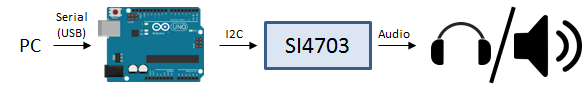
- The SI4703 from Silicon Labs.
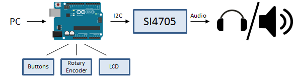
- The SI4705 from Silicon Labs.
- The SI472x from Silicon Labs.
- The SI473x from Silicon Labs.
Download the project files:
The source files for this library is maintained on github in the repository https://github.com/mathertel/Radio.
Here you can browse the source code, issues and discussions. If you like to participate feel free to provide a pull request.
The library can be included into your Arduino development environmwnt by using the Library Manager.
Introduction
This Arduino library implements the software to control some FM and AM radio chips to build the core part of an Open Source FM radio by using an Arduino board.
In fact it is a collection of multiple libraries and samples because there are several chips and breakout boards available these days that can be used to receive FM signals and output an audio signal. I provide a very simple sample for every adapted chip that may help you to start with your setup and some more feature complete sketches that introduce other hardware components like LCD panels and other IO.
Because most of the chips are made for integration into mobile phones or car radios the chips themselves are really small. If you don't have the soldering equipment for these chips you should look out for breakout boards, sometimes together with audio amplifiers for headphones os speakers. The ones I found and listed above
They all are capable for receiving FM radio stations in stereo with European and US settings and can be controlled by using the I2C bus. However there are differences in the sensitivity and quality and well on receiving RDS information from the stations.
For each of these chips a specific library is implemented that knows how to communicate with the chip using the I2C bus and the wire library. These libraries all share a common base, the radio library so that all the common code is only implemented once in there.
All the libraries (for example SI4705.h+SI4705.cpp) share the same interface (defined by the radio.h+radio.cpp library) so it is possible to exchange them when not using one of the chip specific functions.
While implementing the first libraries I found several functionalities being useful for all the chips so these are implemented in the base class too.
However not all chips support the same functionality. For example setting the volume on the TDA chip will not work because this chip doesn't support it. If you query for the result of setting the columns you will always get the default volume level 1.
Other functions are implemented different in different chips. For example the SI4705 chip supports 64 levels of volume while the RDA only supports 16.
Features by radio chip
| Feature | TEA5767 | RDA5807M | SI4703 | SI4705 | ||
|---|---|---|---|---|---|---|
| RADIO | band = FM | X | X | X | X | |
| band = FMWORLD | ||||||
| freq | X | X | X | |||
| mono | X | X | X | X | ||
| stereo | Decode stereo signal | X | X | X | X | |
| RSSI | signal strength indicator | 0 - 64 | 0 - 64 | |||
| SNR | signal noise ratio | 0 – 127 | ||||
| softmute | X | X | X | |||
| mute | X | X | X | X | ||
| Seek | ||||||
| FM Grid | 50 kHz | |||||
| Audio | volume | Supported number of volume levels | 0 - 15 | 0 - 15 | 0 - 63 | |
| bassboost | Boost bass frequencies | X | - | - | ||
| RDS | Data | Decode RDS signal | - | X | X | X |
| Errors | Provide information on RDS signal errors | - | - | X | X |
The Arduino Radio Library
The radio library comes with a bunch of example applications that all show how to use different hardware setups to control the features of the radio chips.
Common to all of these is that the current set of chips have to be controlled using the I2C bus, also known as the "Wire" library.
The Basic Examples
These examples can be found in the Test___ examples delivered with the library.
For starting with your setup I suggest that you start with one of the simple sketches. There is one for each supported chip.
They all initialize the chip, set a constant FM radio station and control the audio settings so that some output should be heated. They all disable the soft mute function so you should be able to hear the white noise if no station is found on that frequency. Modify the code to your favorite or local radio station and upload it again.
A Radio controlled using the Serial interface
This example can be found in the LCDRadio example delivered with the library.
This sketch works with all of the implemented chips by using the common functions. You might have to modify the source code line where the radio variable is defined to the chip you use. There are out-commented lines for every chip in the sketch. Be sure to activate only one line to avoid compiling errors.
The only IO this sketch does is through the Serial interface and when you open the Serial Monitor window of the Arduino programming environment you can see some output from the library and can control the settings by entering commands in the input text line.
The command ? (and enter) will display a short summary of the available commands.
You can see a lot of information using the Serial monitor window including some debugging output for example the new values send into the registers of the chip.
If you like to explore the chip specific settings you may use the "x" command that outputs the chip registers or other chip specific information. Have a look into the chip specific implementation for more details.

The LCD Example
This example can be found in the LCDRadio example delivered with the library.
As with the serialRadio example you have to adjust the code for your chip.
This example implements a full functional radio using an LCD display, a rotary encoder input that aslo has a pushbutton.
Documentation will come soon...
The LCDKeypad example
This example can be found in the LCDKeypadRadio example delivered with the library.
This sketch uses a LCD display shield for IO. It displays the current FM frequency and possible RDS radio information. You can tune the frequency and the volume by using the same commands as with the SerialRadio example.
Documentation will come soon...
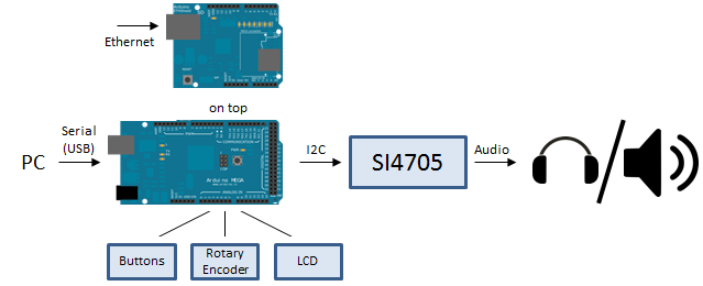
WebRadio
This example can be found in the WebRadio example delivered with the library.
The idea of this very advanced sketch is to build a radio that is connected to the local network and can be controlled by using a web interface:
Because of the huge code size of this sketch it only works fine with an Arduino Mega 2560 board.
Documentation will come soon...
Hardware setup and Wiring
To build up a working radio some hardware setup is required to supply the voltage, control the radio chip, the audio output and probably some additional IO components like buttons or rotary encoder.
Supply voltage
Some of the radio chips are +5 volts tolerant, some need 3.3 volts and some breakout boards come with a regulator and level shifter. You have to read the manual of the chip and the study breakout to find the right connectors and don't put 5 V signals to chips that don't accept that because you destroy them by doing so.
When you need 3.3 volts you can use the supply from the Arduino board. The older boards like the Duemilanove that use the FT232PL USB to serial chip take the internal 3.3 volts regulator of this chip for supplying this voltage.
For the other boards like the Arduino UNO there is an on board regulator that produces this power output.
The 5.0 volts also can be used directly from the board coming directly from USB or from another on board regulator.
However there is not much power available on this outputs. It is possibly enough to drive the radio chip and a headphone amplifier but when you like to drive a power amplifier with some watts you should add a good power supply with low ripple - especially for the audio components.
Wiring the audio output
Some of my boards already have a headphone amplifier on board. Into this connector you can plug some headphones or an active speaker that allows headphone levels as input. I found it easy to use a mini speaker as you can see on several of my photos.
However headphone levels are not exactly what you normally use on a line-in interface to a power amplifier.
Line in levels are using voltage levels into high impedances (1000 Ohms and more). Headphone amps drive voltage levels into low impedances (32 Ohm and lower). So headphone outputs can be used to drive line level inputs and can provide good signals but are typically not as good as true line level outputs.
Newer equipment often allows using mp3 players as an input and can deal with that difference.
Wiring the Arduino and the radio chip
Common to all of the currently implemented chips is that have to be controlled using the I2C bus, sometimes named TWI (Two Wire Interface) also known as the "Wire" library. Beside the GND and the VCC connections as discussed in the Supply voltage this bus needs 2 connections, the data line (SDA) and the clock line (SCL).
The Arduino documentation on the wire library gives enough info to connect the radio board to the right connectors of the used Arduino: www.arduino.cc/en/Reference/Wire
The pins you have to use either depend on the processor of the Arduino or are brought to the SDA (pin 13+3) and SCL (pin 13+4) pins in the newer revisions of the boards. However you have to know that you cannot use the corresponding IO functions (A4&A5 on UNO or D2&D3 on the Leonardo).
If you need 3.3 volts levels from a 5 volts board you should include level shifters.
A port to the Arduino Due or Arduino Zero is planned for a future version. Here everything is already 3.3 volts.
For the SI4703 you also need to add a digital output port of the Arduino to the RST port of the chip. The SI4703 library uses the D2 output by default but you can change that in the source file when you need to.
The usage of the interrupt features (SI4705) is planned for a future version of the library.
Wiring the Arduino to the LCD
Some examples use an LCD for displaying some of the current station information. Using an LCD on the Arduino platform can be done by using the standard LiquidCrystal library that is shipped with the environment. However this library is designed to use a commonly available LCD display (HD44780 compatible) but with a very specific wiring. This is explained in the library documentations.
Because of that wiring that uses a mass of IO ports there are many other solutions available that support the same interface than the original Library (called API1.0). The page playground.arduino.cc/code/LCD tells you a lot about these solutions.
The Radio examples only uses a few of the functions the library offers and should run with the standard and the other API 1.0 compatible libraries without change other than the declaration.
I use a solution that drives the library by also using the I2C bus and a PCF8574 decoder chip.
So search for the library include line:
#include <LiquidCrystal_PCF8574.h>
and put your library here instead.
Wiring the Arduino to a rotary encoder and buttons
To operate a rotary encoder I use the RotaryEncoderLibrary that you can find described in details here: RotaryEncoder Library
On the Arduino Uno I usually use the A2 and A3 ports as input. On the Arduino Mega I prefer A8 and A9. Just search the setup of the encoder in the script files and initialize them appropriate.
RotaryEncoder encoder(A2, A3);
To operate the buttons and especially the pushbutton inside the rotary encoder I use the OneButton library.
OneButton LibraryJust search the setup of the encoder in the script files and initialize them appropriate.
OneButton menuButton(A10, true);
The LCDRadio example is a good starting point to use these input controls.
The RDA5807M from RDA Microelectronics

This was the first FM radio chip I bought. It is available from time to time on eBay and cheap enough to give it a try. My version is placed on a small adapter board with 2 mm spaced connectors and cannot be used on a breadboard without an adapter. So the first action was to build the adapter you can see on the picture.
It works with 3.3 volts and can directly drive a 32 Ohm headphones. The FM receiver is implemented as in combination of analog and digital technologies. The datasheet does not give a lot of details to that. However it can be controlled using the I2C bus, can decode stereo signals and RDS.
There are also adapters available that add some external components. I found that using a capacitor for VCC stabilization had a positive effect so I soldered one directly on top of the module.
There are only a few external parts required. You definitely need the output capacitors. The 3.3 volts power can be supplied by the Arduino board and the I2C bus connections SDA and SCL can be used directly without level shifters. At least I had no problems using them this way. Because the data sheet specifies them to a maximum level of VCC you should consider using a level shifter in between.
To make it more robust I finally soldered it on a permanent board including a 3.3 volts power supply, the capacitors for the output and put it into an Altoids box.
Building the software part was not trivial but after I found the datasheet in Version 1.1 it was possible to enable one feature after the other including the first version of the RDS interpreter.
The SI4703 from Silicon Labs
This was the second chip I bought while searching for more powerful solutions. It's a chip very similar to the RDA5807M but it needs an amplifier to drive headphones. The sound quality and the antenna sensitivity is somehow better.
There is a FM Tuner Evaluation Board with the Si4703 chip available from Sparkfun and you can also find them on eBay. Sparkfun also provides a very simple example for using it with an Arduino board.
https://www.sparkfun.com/products/10663
On this site you can also find a good tutorial: https://www.sparkfun.com/tutorials/293.
This board works with 3.3 volts, has a headphone amplifier and the necessary components. It also can be controlled using the I2C bus and can decode stereo signals and RDS.
There are no further external parts required. The 3.3 volts power can be supplied by the Arduino board and the I2C bus connections SDA and SCL can be used directly without level shifters. You also have to wire the RST signal to a digital output, D2 in my setup.
The SI4705 from Silicon Labs
After a lengthy research on the internet about the design and age of diverse radio chips I found the SI4705 chips from Silicon Labs that offers fare more options than the SI4703.
I bought a module carrying the SI4705 chip as well as voltage regulation and a stereo amplifier for speakers and I2C bus converters
from the German supplier ELV:
https://de.elv.com/elv-fm-receiver-modul-mit-si4705-fm-rm1-komplettbausatz-140984?fs=4116911361.
The board comes pre-assembled and all I had to do is to solder the headers and jumpers. It's easy to solder, all difficult work is done before shipping.
The board doesn't fit good into a breadboard, because of its with. Even if you manage to put it into it would be hard to take it off again. It comes with a sample application for the Arduino that works from the scratch.
The noise on the output is acceptable low and when muting the amplifier can be completely removed from the radio chip. This also gives you the option to use another stereo input from another source but I have not used that feature.
Using the TEA5767
Among all the radio chips I adapted for the radio library the TEA5767 seems to the oldest design and the most simplest and it doesn't support RDS either. I found a cheap board including an TDA1308 headphone amplifier and separate antenna connector on eBay from a Chinese seller and could not resist in buying:
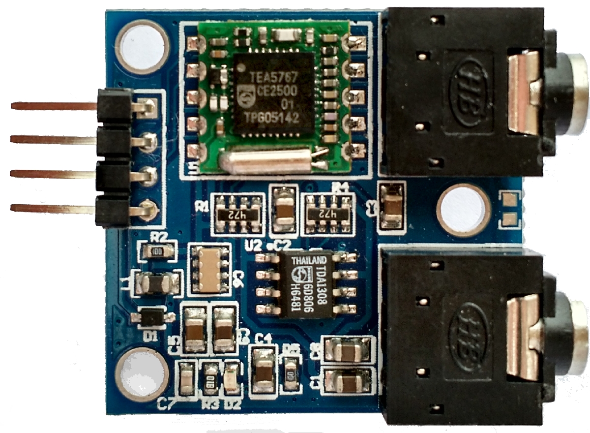
I had heard of this chip already when implementing the RDA5807 radio chip implementation because this chip provides a TEA5767 compatibility mode and can be used as a replacement.
By using the Radio info function you can read the receiver level, the stereo indicator and the current tuned frequency.
The chip doesn't support decoding RDS signals and the audio output is always set to the maximum level and with my board I could easily drive my audio speakers and the line in from an HiFi amplifier. In the library implementation you can find hints for changing the emphasis mode to Europe and us.
Using A Simple Antenna
The simplest Antenna you can build is a 80cm wire for 1/4 wave length or 160cm wire for 1/2 wave length. Better than nothing.
The Web Radio
I like listening to the radio while working at home and prefer music and information over the typical advertising+movies+series mix that is on the tv. So this project was started and ended (up to now) with this implementation.
The WebRadio example is the most complex example I implemented for the Radio Library and is indeed the code tht now runs in the radio next to my working place.
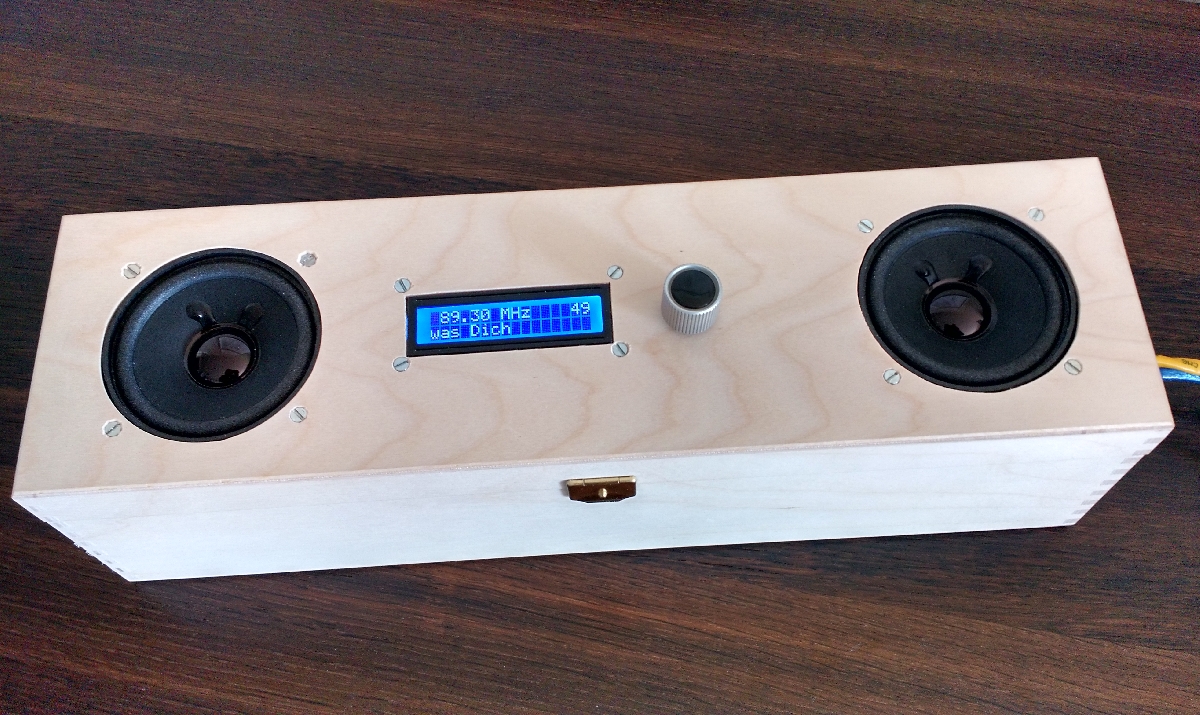
Inside this boy there is a Arduino MEGA with an Ethernet Shield and the SI4705 board from ELV including an amplifier for the speakers. The software also has a lot of technologies that work together:
- The Arduino acts as a web server and listens for http requests.
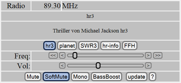
- When requesting for /radio.htm the radio web page is send to the browser that shows the current playing sender, the RDS information and by using the buttons and sliders you can control the settings.
- The user interface is constructed as a HTML page that massively uses the AJAXEngine for the input and output elements.
- This web page contains an OpenAjax hub implementation that links all the active elements together.
- The web server uses the SD card for storing the files.
- You can upload new and changed files to the SD card for updates "in the field".
- The client-server communication is based on JSON packets over http.
- The webserver can be asked for the current information from the radio chip and RDS parser that i displayed in the web front end.
- The webserver can be told to change the volume, the station and some options like mute and mono.
- All the radio chip is controlled according to the values received by the web server.
- A LCD display is used to display the current sender information.
- A rotary encoder can be used to change channel and volume.
- Multiple browsers can connect to the radio (server) at the same time.
- The USB port gives debugging information and can be used to control the radio too.
The code for driving the radio chip, the LCD m the rotary encoder and the serial interface is essential the same as in the LCDRadio project. Rellay new to this example is the web server implementation that covers all kind of http communication. Soe the main explaination for this example really goes to the web server implementation.
This sketch is the largest I wrote for the Arduino and it doesn't fit into the program memory and RAM of an Arduino UNO so I had to use an Arduino MEGA. Especially RAM helps to speed up the web server.
Implementing the multiple tasks in one sketch
When implementing a complex sketch that handles mutliple IO devices it is a good idea to implement a separate loop function for every IO component. These specific loop functions can implement the proper functionality for this IO device and should return as fast as possible.
In the global loop() functions all the sepcific loop functions are called in a row to give every component the chance to run:
/// Constantly look for the things, that have to be done.
void loop()
{
  unsigned long now = millis();
  loopWebServer(now);  /// Look for incomming webserver requests and answer them...
  loopButtons(now);    /// Check for changed signals on the buttons and rotary encoder.
  loopSerial(now);     /// Check for serial input commands and trigger command execution.
  loopRadio(now);      /// Check for new radio data.
  loopLCD(now);        /// Check for new LCD data to be displayed.
} // loop()
Implementing a web server
There is a basic WebServer example comming with the library for the Ethernet Shield. It's very simple and shows the basic structure for waiting for new server requests and how to answer them by sending data back to the client. However there are some things that have to be changed for a good performing webserver.
When writing network applications it is really important to look into the network layer and check the results. I did that with the Wireshark tool that can sniff all packets on the network. So here are some things I discovered and like to tell you (not to do).
Actively closing connections
After sending a http answer back to the client it is important to stop the communication on the TCP level by closing the client connection using the stop() function. This helps in cleaning up the incomming requests. In some cases the browser side doesn't close the connection by itself and because Arduino only can answer to one client at a time this trick helped to fix a lot of hanging requests. This is a http 1.0 compatible behaviour.
In multithreading web servers (IIS, Apache Tomcat, ...) in contrast it makes more sense to keep the connection and reuse it.
Reading from the SD card
Some WebServer implementations you can find code like this:
client.write(file.read()); // send web page to client
Here the content of the file is read from the SD card one byte at a time. There is a huge overhead in that function just to find the next byte available that has to be executed every time. A better approach is to use another function that passes a buffer:
len = file.read(buffer, sizeof(buffer))
client.write(buffer, len);
It’s up to 10 times faster to work with a buffer.
Sending strings from PROGMEM
It seems so easy defining strings in the PROGMEM space to save memory from the ram. Here is an example that works:
#define HTTPERR_404   F("HTTP/1.1 404 Not Found\r\n")
_client.print(HTTPERR_404);
When looking at the packets of network data by using a sniffer you can see that all the characters of the string are sent out one by one in a separate package. This is because the characters are pulled out of the PROGMEM or Flash space one by one and immediately sent out causing a 1 char package on the net as you can see in the log of a network sniffer:

The 60 bytes packages only transfer one character payload. So it is necessary to avoid using F() strings as a parameter - but wait for the StringBuffer!
The StringBuffer class
The main problem with the speed of an Arduino as a web server is to use optimized approaches for sending out data that is normally text. So I have built a helper class called StringBuffer that helps filling small text fragments into a larger string and sending out that string only at the end using only one call to the client.
Have a look at the functions this library offers. It’s not a library and you can add the StringBuffer.h file to your own sketch and use / extend the functions easily.
Sending out using multiple client.print calls
The first implementation of the “file not found” situation was:
// Response no and send not found html
void respondHeaderNotFound()
{
  client.print(HTTPERR_404);
  client.print(HTTP_GENERAL);
  client.print(HTTP_ENDHEAD);
} // respondHeaderNotFound()
And this ended in 84 packets with on character using up to 60 bytes for the complete packet.
Very network consuming :-( and slow too :-((
By using the StringBuffer implementation it is possible to collect all the text and sending it out in one piece:
// Response no and send not found html
void respondHeaderNotFound()
{
  StringBuffer sout = StringBuffer(_writeBuffer, sizeof(_writeBuffer));
  sout.append(HTTPERR_404);
  sout.append(HTTP_GENERAL);
  sout.append(HTTP_ENDHEAD);
  client.print(_writeBuffer);
} // respondHeaderNotFound()
Now only 9 packets are sent out:

The possible Ethernet Shield Problem
With one of my Ethernet shields I had the problem that the ethernet communication was unable to start. The problem lies in the reset mechanism and is described in the Arduio forum: http://forum.arduino.cc/index.php?topic=28175.msg208411#msg208411
The propose to add another 100nF capacitor to the reset line and ground.
After changing the Ethernet shield to a newer board revision the problem disappears so swapping the board may also solve the problem.
ChangeLog
- 06.04.2015 First published version.
- 12.05.2015 stable version with additional documentation.