DMXSerial Arduino Library for sending and receiving DMX
This is a library for sending and receiving DMX codes using the Arduino platform or a ATmega (ATmega168, ATmega328 or similar) processor with a clock speed of 16 MHz.
The library avoids timming issues on the low level protocol that typically exist when using software implementations by using the internal serial communication hardware of the chips. Therefore it is very uncritical to add you specific DMX effects on top of this communication library.
DMX sending and DMX receiving are both supported by this library. You can find a brief description of using the details of the serial hardware registers in this article.
Download
Use the Library Manager from the Arduino environment to download the library files including 4 samples for sending and receiving DMX messages.
By using the Library Manager built into the Arduino Environment you can always download the latest stable version that comes directly from the github repository:
https://github.com/mathertel/DmxSerial
If you like the latest version including work in progress or like to contribute using pull requests please clone the project from github directly.
A API documentation of the DMXSerial class is also available.
Using the DMXSerial library
The DMXSerial library supports the following modes of operation:
DMXController mode -- This mode is starting the Arduino in DMX sending mode state and immediately starts sending the data stored in the internal buffer to the serial interface. This is done in the background by using the interrupts that are triggered when a data package has been sent for sending the next data package or a BREAK condition to start a new DMX package.
To use this mode, just start the library in this mode and implement a loop in your sketch that updates the data.
Even when no data is changed the DMXController mode will send out another package of data immediately after finishing one.
DMXReceiver mode -- This mode is starting the Arduino in DMX receiving state and immediately starts receiving DMX data and storing received values into the internal buffer. This is done in the background by using the interrupts that are triggered when a complete data package has arrived or a break condition has occurred.
DMXProbe mode -- This mode is starting the Arduino in DMX receiving state, but doesn’t actively listen for incoming data. No interrupts are enabled and any incoming data packet will stick in the serial receiver. To receive data the receive() function must be called. This function clears all hardware buffers and waits for an incoming data package by using the same mechanism as the DMXReceiver mode. After receiving a package this function returns with true and data can be found in the internal buffer. When no DMX data was received in the specified time the receive function will return false.
Examples
There are examples available that show how to use the library to implement your sketches:
DmxSerialRecv
This example shows how to implement a DMX device that just retrieves 3 channels for a RGB LED.
If you use the DMXShield you can use the availabe RGB pins for testing purpose.
DmxSerialSend
This example shows how to implement a DMX controller that just send out constantly changing values for 3 channels for a RGB LED.
If you use the DMXShield you can use the availabe RGB pins for testing purpose.
DMXSerialFlow
This is an example shows how to send a more complex RGB based pattern of colors over a DMX line. Actally there are 60*3 values constantly changed for a series of 3-channel devices receiving Red-green-blue RGB values.
The values for one of the channels can be watched at the PWM outputs of the Arduino Board.
DmxSerialNeoPixels
This example contains a sketch for receiving DMX data with an Arduino and sending the received values to a series of NeoPixel or WS2811 LEDs.
Hardware
This sketch and library shows how to use the hardware serial interface for sending and receiving DMX data packages.
To have a minimal DMX compatible hardware you have to add a RS-485 driver chip like the MAX481 and attach it to the hardware based serial interface of the ATMEGA Microcontroller. A corresponding Arduino compatible DMX Shield can be found at DMXShield.
The library supports another output pin (D2 by default) that allows switching the DMX data direction. This allows building a shield that supports both directions and can be switched by software.
DMX and RDM
DMX521 or DMX in short was defined to control stage lightning effects by using XLR style cables. A good starting point for more information about the history and evolution of DMX can be found on Wikipedia: http://en.wikipedia.org/wiki/DMX512
Some Arduino related information is also available on the playground of the Arduino WebSite: http://www.arduino.cc/playground/Learning/DMX
While DMX was designed to have a single sender and multiple receivers. In 2006 a bi-directional protocol called RDM was defined that enhances DMX that enables a bi-directional communication that I like to support as well. See also: https://en.wikipedia.org/wiki/RDM_(lighting)
Both, the hardware and software decisions and designs were made to support RDM and DMX and die Arduino Shield can be used for all of it.
With this first version however only DMX Controllers (only sending) and DMX Receivers (only listening) are supported mode of operations.
Before starting the soldering and programming I did some research on existing DMX interface projects and checked for good and bad design hints.
DMX protocol levels
The logical level of DMX communication is built upon serial sending with 250.000 baud according the RS-485 definition using no parity bits and 2 stop bits.
Luckily the hardware serial ports built in the ATMEGA chips used on the Arduino board supports this kind of communication and this high baud rate. see also http://en.wikipedia.org/wiki/RS-485
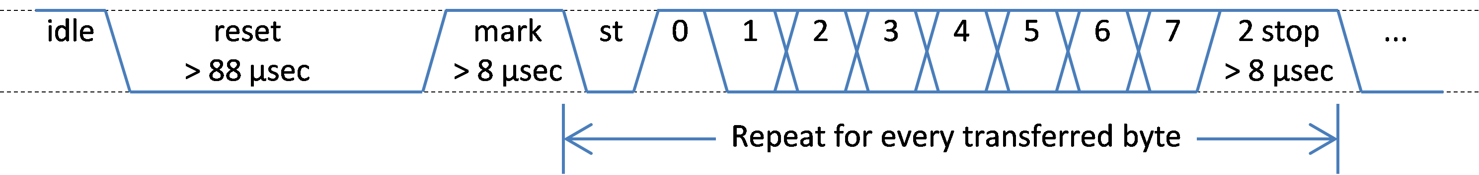
There is nothing really special about the levels of this communication protocol except the reset frame which is low for more than 88 µsec. The 2 stop bits have a minimum time of 8 µsecs but this time can be longer up to one second.
After a reset frame the payload bytes are transmitted by the DMX host using a start byte (value 0) and maximum of 512 channel value bytes. It is not recommended to send less than 24 channels.
This DMX and RDM specification allows sending and receiving DMX by using the built-in hardware. The tricks we need will be explained further down.
Conflict with Arduino Serial implementation
The DMXSerial libraries relies on the hardware based serial interface (USART) and the corresponding interrupt routines that is provided by the CPUs. When you use the standard Serial implementation of the Arduino this may result in conflicts on registiering these interrupt routines that you can find in the compiler output like:
HardwareSerial0.cpp.o (symbol from plugin): In function `Serial':
(.text+0x0): multiple definition of `__vector_18'
Arduino Uno -- based on the ATmega168, ATmega328 or similar offers only one Serial port that is also used by the USB to Serial chip for uploading and Serial output. The DMXSerial compiles successfully when you do not use the Serial implementation at all. Some 3rd party libraries also use the Serial port internally or by accident and create such a conflict.
Arduino Leonardo -- this board uses a chip that has a USB 2.0 port available in addition to the USART. Therefore the “Serial” port is routed through the USB port that behaves like a serial port device and not the built-in USART. On this board the DMXSerial library uses the serial port 1, also available on pins 0 an 1. If you address the real Serial port Serial1 but will create the conflict above.
Arduino MEGA 2560 -- this board uses the Mega2560 processor that offers multiple USART ports. The DMXSerial library uses the USART0 port by default using the pins 0 and 1 - same as the UNO board.
You can switch to port 1 using the USART1 by changing one line in the file DMXSerial_avr.h. Just uncomment the line (~33):
#define DMX_USE_PORT1
Arduino Nano Every -- This board uses the MEGAAVR4809 processor and comes in a format like the Arduino nano. The DMXSerial library uses the USART1 port by default on this processor.
When you use a free USART port or used software based Serial transmissions you will probably see that the DMX communication fails. This is often caused by the fact that these implementations use interrupt routines as well or disable interrupts for a specific time. However, DMXSerial needs to respond to all interrupts from the DMX port to get all data from the DMX line.
Using the serial interface through registers and interrupt routines
There are several hardware settings that have to be implemented to enable the built-in serial interface to be used directly. Here I just go through the implementation for your orientation how it's done.
Sending and receiving DMX The logical level of DMX communication is built upon serial sending up to 512 bytes by using 250.000 baud timings no parity bits and 2 stop bits. Luckily the hardware serial ports built in the ATMEGA chips used on the Arduino board supports this kind of communication and this high baud rate.
Enabling the hardware has to be done by setting the corresponding bits in the USART Control and Status Register B. The following does enabling sending and the corresponding Data Register Empty Interrupt in the case of the DMXController mode:
// Enable transmitter and interrupt
UCSRnB = (1<<TXENn) | (1<<UDRIEn);
Enabling the receiver and the corresponding Receive Complete Interrupt in the case of the DMXReceiver mode is very similar:
// Enable receiver and Receive interrupt
UCSRnB = (1<<RXENn) | (1<<RXCEn);
Setting the baud rate is implemented in the function _DMXSerialBaud because we often have to change it when sending DMX packages. The source code of this function is very similar to the one used in the standard Serial implementation, except that it also sets the transmission mode to 2 stop bits, 8 data bits and no parity:
// initialize the Hardware serial port with the given baud rate
// using 8 data data bits an 2 stop bits.
void _DMXSerialBaud(long baud)
{
  uint16_t baud_setting;

  // calculate baud settings
  baud_setting = (F_CPU / 8 / baud - 1) / 2;

  // assign the baud_setting to the USART Baud Rate Register
  UBRRnH = baud_setting >> 8;
  UBRRnL = baud_setting;

  // 2 stop bits and 8 bit character size, no parity
  UCSRnC = (1<<USBSn) | (3<<USCZn0);
} // _DMXSerialBaud
Sending a byte using the hardware is done by writing a new value into the USART Data Register after checking that there is no current transmission.
void _DMXSerialWrite(uint8_t data)
{
  // Wait for empty transmit buffer
  while ( ! (UCSRnA & (1 << UDREn)) )
    ;
  // Put data into buffer, sends the data
  UDRn = data;
} // _DMXSerialWrite
Where you can find details about this line of code
In the official documentation from ATMEL for the ATmega328P microcontroller there is a chapter 20 about the internal Universal Synchronous and Asynchronous serial Receiver and Transmitter (USART) starting on page 178. There are also microcontroller chips in the ATmega family that have more than one USART, so the USART also is referenced by the USART with number 0 (USART0).
In the block diagram you can see that there are some software addressable registers (in bold) used to configure these ports. The name of the registers are UBRRn, UDRn, UCSRnA, UCSRnB and UCSRnC where n is the placeholder for the number of the USART. The concrete registers for the USART0 are:
UBRR0H and UBRR0L: Baud Rate Registers
UDRn: I/O Data Registers
UCSR0A: Control and Status Register A
UCSR0B: Control and Status Register B
UCSR0C: Control and Status Register C
In chapter 20.11 Register Description you can find a short description of each register does.
The Arduino Serial library takes care of many configuration settings when initialized by calling Serial.begin([baud rate]). In the folder \hardware\arduino\cores\arduino you can find the file HardwareSerial.cpp with the implementation of this library. You can search for the begin method and can see that the baud rate is used to calculate the values for the registers UBRR0H (_ubrrh) and UBRR0L (_ubrrl) and some bits of the register UCSR0B (_ucsrb) are set. There is no initialization of the Control and Status Register C at all.
This line of code sets the serial communication mode to asynchronous mode (UMSEL01 and UMSEL00 are not set), no parity mode (UPM01 and UPM02 are not set), 2 stop bits (1<<USBS0) and 8 bit character size (3<<UCSZ00).
The Receive interrupt routine
Receiving a byte is not implemented using a function, instead a interrupt service routine is registered and will be called when a data package was detected and received by the hardware. No CPU cycles are needed for waiting. The received data is available in the USART Data Receive Register UDRn and a potential buffer overflow that will happen when receiving the DMX reset signal is available in USART Control State Register A UCSRnA. Both values are stored to local variables for later use:
ISR(USART_RX_vect) {
uint8_t USARTstate= UCSRnA; //get state before data!
uint8_t DmxByte = UDRn; //get data
...
}
The Sending interrupt routine
This interrupt routine is called by the hardware just after a byte was completely sent. This routine will then check for the next byte that has to be sent out. In DMX Controller mode the routine starts again with sending the reset signal when all data of the complete package is sent.
ISR(USART_UDRE_vect) { ... }
Sending the reset
The standard Arduino chip supports the 250.000 baud transfer rate that is used by DMX. The only exception to a plain 250.000 baud communication this is the BREAK / reset signal that is a physical low level on the wire for more than 88 µsec.
This 88 µsec low signal cannot be sent by using the 250.000 baud rate. For sending the break a slower baud rate is initialized, a 0-byte is sent and the baud rate is reset to the correct 250.000 baud.
// setup a slower baud rate
_DMXSerialBaud(115200);
// and send a 0 byte
_DMXSerialWrite((uint8_t)0);
After the BREAK has been sent the following code switches back to 250.000 baud for sending the data bytes:
Serial.begin(250000);
Serial.write((uint8_t)0);
The second problem with the format used by DMX is the number of stop bits. Normally when using the serial port only one stop bit is used. Adding a second stop bit cannot be done through a configuration parameter or library call but must be done by adjusting the hardware setting for the serial port 0:
UCSR0C = (1<<USBS0)|(3<<UCSZ00);
You can find this code in the interrupt service routine to start a complete DMX package and continuously sending out the DMX values in the DMXController mode.
A design for a DMX Shield that works with this library can be found in the article: DMXShield.
How to detect, that a device is disconnected?
It is not possible to detect that no cable is actually attached to a device without adding more hardware. So there is a more soft (software based) solution for that.
When a DMX start packet is received the library remembers the current time to a static variable. By using this value the method "DMXSerial.noDataSince()" the returns the number of milliseconds since the last packet was received.
The time is calculated by using the millis() function.
In the main loop or anywhere else you can check if the DMX signal was received during the last time and react if it is too long ago.
In the DmxSerialRecv sample there is a call to the function for showing a fallback color (red in my case).
Links
-
DMX on the Arduino website. A good starting point for research:
http://www.arduino.cc/playground/Learning/DMX -
About the HSL HSV and RGB Color models:
http://en.wikipedia.org/wiki/HSL_and_HSV -
The documentation for the ATmega328P microcontroller can be found at:
http://www.atmel.com/dyn/resources/prod_documents/doc8271.pdf -
RS-485 description
http://en.wikipedia.org/wiki/RS-485 -
DMX description
http://en.wikipedia.org/wiki/DMX512 - MAX481 and MAX485 from MAXIM: http://www.maxim-ic.com/datasheet/index.mvp/id/1111
-
Details on how to use the library with ARDUINO MEGA and ARDUINO Leonardo boards and different ports:
http://mathertel.blogspot.de/2013/05/update-for-dmxserial-library.html
History
- 24.08.2011 First published version.
- 04.12.2011 Updated for compatibility with the Arduino 1.0 environment.
- 10.05.2012 Added the method DMXSerial.noDataSince()
- 04.06.2012 Now initializing the register UCSRnA to 0 correctly to avoid problems with Arduino Unos double speed baud settings.
- 11.08.2012 Update to adjust some timing conditions and optimizations. Thanks a lot to Jonathan L.
- 19.05.2013 Update to support multiple boards and configurations: MEGA 2560, Leonardo etc.
- 19.05.2013 Update to support ATmega8 chips (still beta).
- 01.07.2013 Added another example sketch.
- 26.08.2013 Some minor fixes.
- 03.09.2017 New DMX mode that pauses DMX receiving for some time. Example for controlling NeoPixel and WS2811.
- 27.05.2020 MEGAAVR4809 support. Some rewrite of the code to separate processor code from DMX protocol handling.
- 23.10.2021 some documentation added.